The following case is based on a paper, "
Challenges in database design with Microsoft Access", published in
Journal of Instructional Pedagogies. The database design example is based on the Pine Valley Furniture case presented in textbook
Modern Database Management by Hoffer, J. A, Prescott, M. B., McFadden, F. R. , Seventh Edition. Upper Saddle River, New Jersey: Pearson - Prentice Hall, 2005.
DATABASE DESIGN PROCESS
Building a data model (EERD), using systems like MySQL Workbench, depends more on the subject-matter (domain) expertise than on the database skills. A subject-matter expert, who understands simple concepts of an entity (or class) and relationship can decidedly contribute to development of the data model. The following example shows a simulated scenario
of the database design process with two participants: a domain expert (a sales manager,
Mark) and database expert (a database administrator,
Debbie).
Mark: “I have been managing my sales for quite some time, using a phone and spreadsheet based ordering system. Recently, I have read some interesting articles about how my job can be improved by switching to a Web based system.”
Debbie: “You understand that a Web system requires a multiuser and concurrent access to your data! Thus you can’t use your spreadsheet program. You would have to move to a database solution.”
Mark: “Yes, I have read about that too. Can you help me with designing a database? I’d like to see, for example, how basic information about customers, orders and products can be stored in the database.”
Debbie: “Absolutely! Could you briefly explain how your system works? At this stage, let’s us focus on capturing and modeling information about orders.”
Mark: “It is quite simple. We maintain a list of customers and products. Our customers place orders from time to time. We make sure that each order belongs to one and only one customer. The orders include some of our products—mainly small pieces of furniture (desks, chairs, shelves, etc.). Each product may be part of many orders.”
Debbie: “I get it! Would you agree that your basic data entity sets (or object sets) are: Customer, Order and Product?
Mark: “Indeed they are! As a matter of fact they are already maintained in our current system as spreadsheet lists. Our customers are mainly businesses so we store ‘name’, ‘addresses’, contact information (‘phone’, ‘fax’, and ‘email’). Our orders includes ‘order date’ and reference to the customers who placed them (‘cid’). Finally, our products are characterized using such properties as ‘description’, ‘finish’, ‘unit price’, and ‘quantity on hand’. ”
Debbie: “Great! You can also say that they (entity sets) are organized as tables. If so, they will be organized in a database in almost the same way—as database tables. We have to make sure that all rows in the tables are unique. To this end, for each table, we will create an identifier that, as you probably know, is referred to as a Primary Key (PK).”
Mark: “I thought it would be much harder. In fact, we use integers to identify particular rows in the spreadsheet tables so we could easily look up relevant data, for example, when generating invoices. Our identifiers are: ‘cid’ (customer ID), ‘poid’ (Order ID), and ‘pid’ (Product ID).”
Debbie: “Outstanding! Indeed, a spreadsheet lookup procedure comes very close to what we refer to in a database as a relationship. Later, in the database, you will be able to generate invoices by just using relationships, speaking of which, you have already mentioned the most important ones. Let me formalize them, using already established entity sets, as:
<Customer(1) – places – Order(1..n)>
<Order(0..n) – includes – Product(1..n)>
Mark: “I kind of get it but not entirely.
Debbie: “The first relationships is of type ‘one-to-many’. As you mentioned, a customer may place one or many orders (1..n). In the same time, each order belongs to one (1) and only one customer. The second relationship is of type ‘many-to-many’. One order may include many products (1..n) and one product may be part of zero or many orders (0..n). These entities and relationships plus the attributes you mentioned above are all we need to construct a data model—the so called Entity Relationship Diagram (ERD). I will show you how to do it, using MySQL Workbench. The first step is to define the basic entities: Customer, Order and Product. Start MySQL workbench, create a new EERD model and, using the Table tool add the three entities, providing their names and attributes. Make sure that each entity has its own PK (Primary Key). Figure 1 shows the resulting diagram. Notice that, contrary to a spreadsheet implementation, each of the attributes must have appropriate type. The generic types (INT, FLOAT, DATETIME) are obvious. VARCHAR and CHAR stand for text types. The former specifies the maximum size (capacity) and the latter—the exact size. Next, the relationships between the entities must be defined. They are a reflection of business. The Customer - Order relationship is created, using a Non-Identifying, One-To-Many relationship (1..n) and by connecting entity Order with entity Customer. A new attribute is added automatically to entity Order: Customer_cid (Figure 2).”
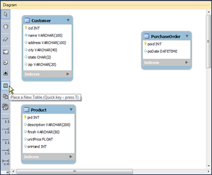 | 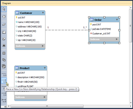 |
| Figure 1. The basic components (entities) of the data model. A new table is created using the New Table tool. | Figure 2. Connecting entity (table) Order with Customer. A foreign key, Customer_cid, is added automatically to table Order. |
Mark: “Why is the Non-Identifying Relationship used here? What does it mean? “
Debbie: “Both the entities (Customer and Order) are already identified by their primary keys (cid, and poid). The additional field, Customer_cid, added to entity Order does not uniquely identify any order. It simply points to the customers that ‘own’ the orders.”
Mark: “It makes sense. What about the new attribute, Customer_cid? It looks like a copy of the primary key ‘cid’ in entity (table) Customer. In our spreadsheet implementation we use a similar approach in order to be able to lookup customer information in our invoices.”
Debbie: “Indeed it acts like a copy. Such an attribute is called a Foreign Key (FK). Its role is to make sure that each order ‘knows’ its owner. One can also say that each order matches (Harkins, 2004) its customer. In addition, the database system should ensure that each value of this attribute is one of the values of the related primary key, ‘cid’ defined in table Customer. This kind of validation is referred to as Referential Integrity. It is also important to note that this new key, Customer_cid, is strictly connected to the relationship between entities Order and Customer. Removing the key will also remove the relationship (connection line) and vice versa.” It is very important to understand that a foreign key only exists in the context of a relationship. It is a property of an entity (table) whose instances (records) depend on or are spawn by an instance of the related entity. With respect to the Customer – Order relationship, a customer places (creates) one or more orders. Each order is ‘signed’ by one customer. This signature is represented by the foreign key, pointing uniquely to one and only one customer.”
Mark: “I guess, I got it!
Debbie: Morover, the PK-FK pairs reflect particular relationship instances which arise from business operations (rules). One can say that the role of the Primary Key is to maintain the Entity Integrity and the role of the Foreign Key is to ensure the Referential Integrity. Unlike spreadsheets, databases help us maintain data integrity. Our next step is to take care of the second relationship (Order – Product). This time we will use a Many-to-Many Relationship tool (‘n..m’). There is only one version of this tool: the Identifying Relationship. When two entities are connect with this tool, a new entity is spawned as shown in Figure 3. This is a so called associative entity. It may not exist on its own. Both the entities, Order and Product, are needed for this new entity to exist. Its business role is to ‘know’ which product is part of which order. It is frequently described as an order detail, invoice line, or order line. We will use the latter (OrderLine) to name this new entity.”
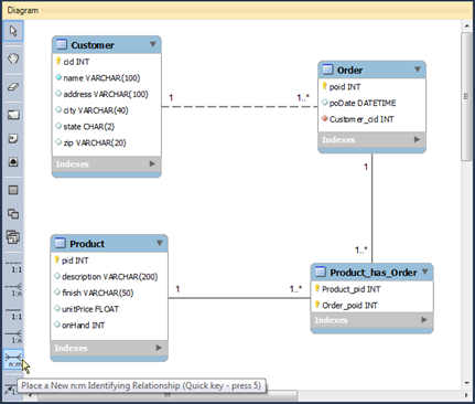 | 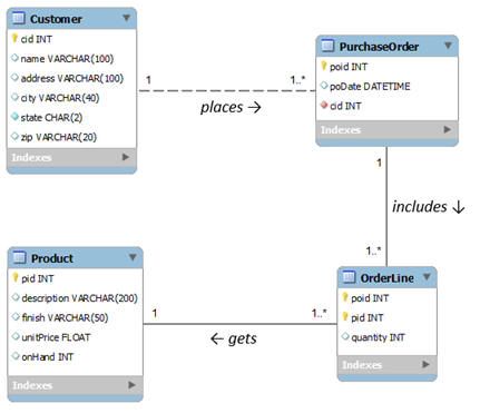 |
| Figure 3. Resolving a Many-to-Many relationship. The 'n:m' tool connects entities Product and Order, generating and associative entity (Product_has_Order). | Figure 4. A data model (EERD) of a product ordering system. |
Mark: “This all sound reasonable. I can see that we are almost there. There is one extra piece of information missing. We should not forget to add the ‘order quantity’, or just ‘quantity’ to this new entity (OrderLine).”
Debbie: “Excellent! This is why domain experts should always participate in database design processes. Like nobody else, they know the business rules and can anticipate what information will be needed in order to perform all sorts of business operations and decisions. To wrap up our design, let us rename the new entity and new attributes. I would also recommend to rename entity Order to PurchaseOrder. Some systems, like MySQL, do not accept user defined names that coincide with reserved word (e.g. Order). We could also use a name that we know from our online shopping experience: ShoppingCart. Figure 4 shows the final version of the model. By the way, the EERD example, shown above, is a logical data model expressed in UML. Since many database developers also develop applications, using Object-Oriented language it is convenient for them to express the model, using the Object-Oriented design language—UML.”
Mark: “So now, how do we convert this model into a ‘real’ database?”
Debbie: “With MySQL, we can automatically generate the database structure or what it is known in the database ‘world’ as the database schema. This is why the model, we have just created, is called an ‘Enhanced’ Entity Relationship Diagram. Using the data model, like the one shown in Figure 4, a database expert should be able to develop manually appropriate SQL - CREATE TABLE statements that would create the database schema. MySQL Workbench can generate such statements automatically from the EERD model. The resulting statements are fully compatible the MySQL database system.”
CREATE TABLE IF NOT EXISTS `Customer` (
  `cid` INT NOT NULL,
  `name` VARCHAR(100) NOT NULL,
  `address` VARCHAR(100) NULL DEFAULT NULL,
  `city` VARCHAR(40) NULL DEFAULT NULL,
  `state` CHAR(2) NULL DEFAULT NULL,
  `zip` VARCHAR(20) NULL DEFAULT NULL,
  PRIMARY KEY (`cid`));
ENGINE = InnoDB;
CREATE TABLE IF NOT EXISTS `Product` (
  `pid` INT NOT NULL,
  `description` VARCHAR(200) NULL DEFAULT NULL,
  `finish` VARCHAR(50) NULL DEFAULT NULL,
  `unitPrice` FLOAT NULL DEFAULT NULL,
  `onHand` INT NULL,
  PRIMARY KEY (`pid`))
ENGINE = InnoDB;
CREATE TABLE IF NOT EXISTS `PurchaseOrder` (
  `poid` INT NOT NULL,
  `poDate` DATETIME NULL DEFAULT NULL,
  `cid` INT NOT NULL,
  PRIMARY KEY (`poid`),
  CONSTRAINT `fk_Order_Customer`
    FOREIGN KEY (`cid`)
    REFERENCES `Customer` (`cid`)
    ON DELETE NO ACTION
    ON UPDATE NO ACTION)
ENGINE = InnoDB;

CREATE TABLE IF NOT EXISTS `OrderLine` (
  `pid` INT NOT NULL,
  `poid` INT NOT NULL,
  `quantity` INT NULL,
  PRIMARY KEY (`pid`, `poid`),
  CONSTRAINT `fk_Product_has_Order_Product1`
    FOREIGN KEY (`pid`)
    REFERENCES `Product` (`pid`)
    ON DELETE NO ACTION
    ON UPDATE NO ACTION,
  CONSTRAINT `fk_Product_has_Order_Order1`
    FOREIGN KEY (`poid`)
    REFERENCES `PurchaseOrder` (`poid`)
    ON DELETE NO ACTION
    ON UPDATE NO ACTION)
ENGINE = InnoDB;
Mark: This is impressive, transforming a picture to a database schema! How is it done?
Debbie: After completing and saving the model, all you need is to press
Ctrl+G and complete intuitive dialog commands, in order to generate and execute the schema. if MySQL Workbench is connected to the server, it will automatically create the database. This case is more about designing a database. Detail steps about transforming this model to SQL and to a physical database are shown in TBD. The following link will let you download the model as an EERD document:
MySQL Workbench Data Model.